
Introduction
Back in 2016 I installed a steel pier in my back garden in an effort to both improve my longer exposure images and also reduce setup time. Having a pier worked brilliantly for both objectives. After two years I now take the 5 minute setup time for granted and have hunger to shorten this further.
The logical next step was to have all of my equipment permanently mounted. There are a number of options to do this but the most common would be:
- Shed with Roll off Roof.
- Shed that can be removed.
If I was starting from scratch I would likely have gone with the first option, mostly because it offers some great advantages; like being able to work at the system even when the weather is poor but also it is easy to motorise. Alas, this wasn’t such a clear winner for me.
My current astro-shed is 10x10’ and houses lots of other non-astronomy related equipment, smart tv, server rack, etc. Reworking the roof of this shed would be a significant undertaking, especially with the unreliable UK weather!
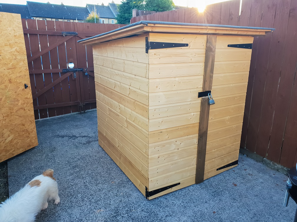
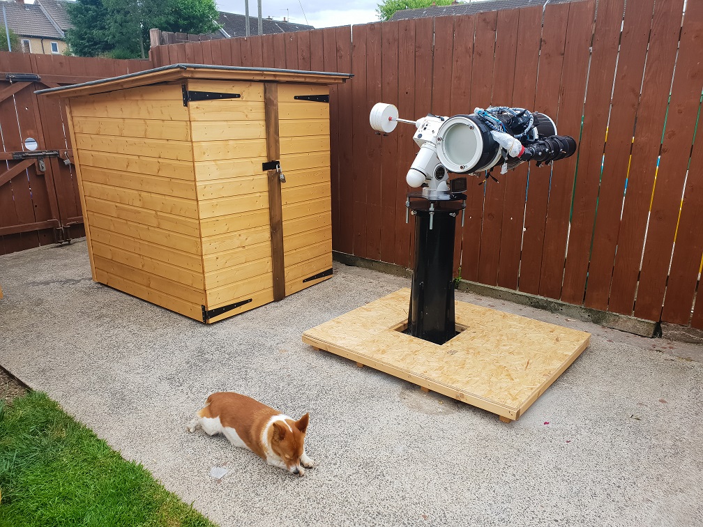
I ended up deciding that I would build a ‘shed on wheels’ that could be removed from the pier at a moments notice and I could be up and running straight away. One big advantage of this design is that there are no walls to contend with, the shed does not obscure views in any direction. I spent a couple of months towards the end of the 2017/2018 season drawing / 3D modelling a few designs that I liked, eventually settling on a simple roughly square shed with a single sloped roof. I did consider making a small shed with roll-off roof but decided against this simply because of the footprint it would require… I need to leave some room for my kids to play!
Materials
- 2x2” Rough Timber for frames
- 12mm Weatherboard for walls & doors
- 12mm Plywood for roof
- 12mm OSB for floor
- 25x10mm lathe for trimming under roof
- 4x0.75” Rough Timber for door astragal (overlap)
- Polyester based Roofing Felt
- Felt Adhesive
- 182mm hinges (Modified to suit door design)
- 52mm Fixed Castor Wheels (6x)
- Hasp & Staple & Drop-bolts
- Nails: 3”, 1.25” & 1”
- Screws: 4”, 3”, 2” & 1.5”
The Build
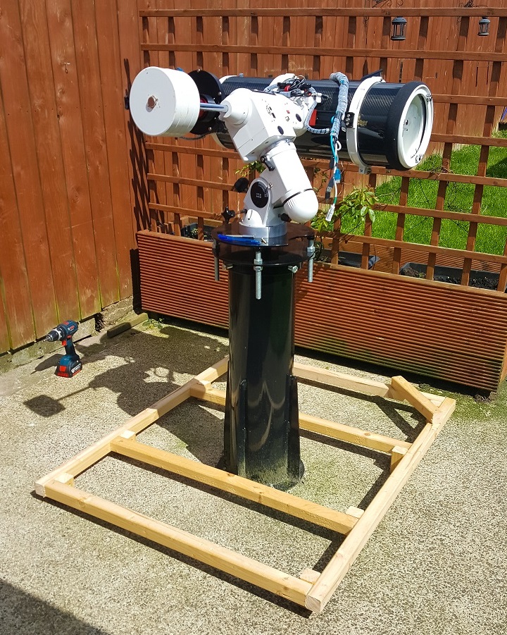
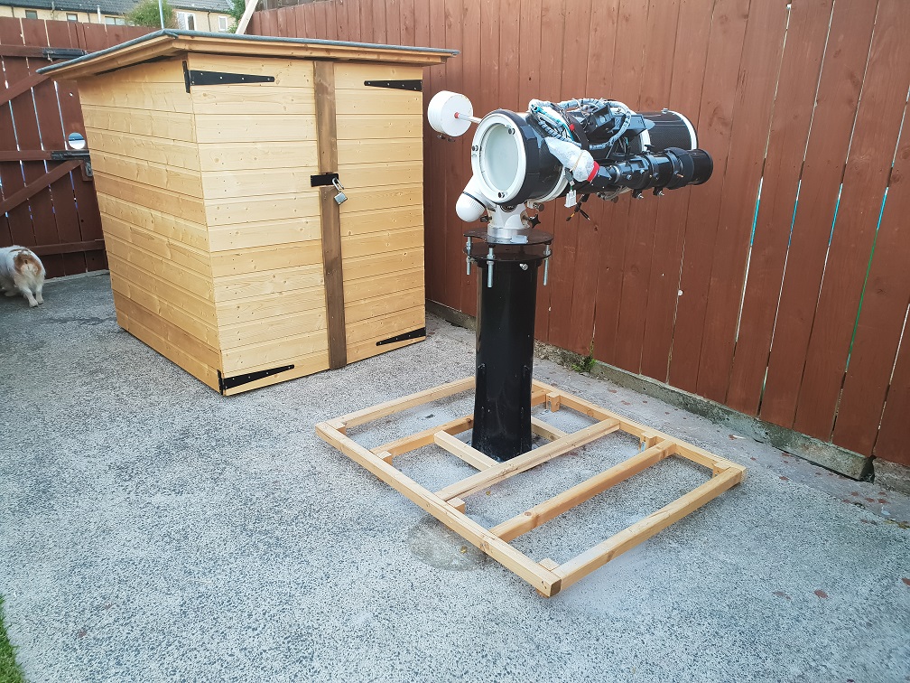
Being an ex-mechanical engineer I am very comfortable with designing structures, the actual fabrication takes a bit more effort however. The first task was to get the equipment ‘parked’ in the position I would intend it to be in when the shed was closed & then build a base to build around, see photo below. I did some reading online to confirm my suspicion that if the mount was parked and balanced it would be fine sitting in this orientation for long periods of time. As my concrete has a slight slope to it, so rain doesn’t puddle on it, I needed to level everything up and allow for this slope.
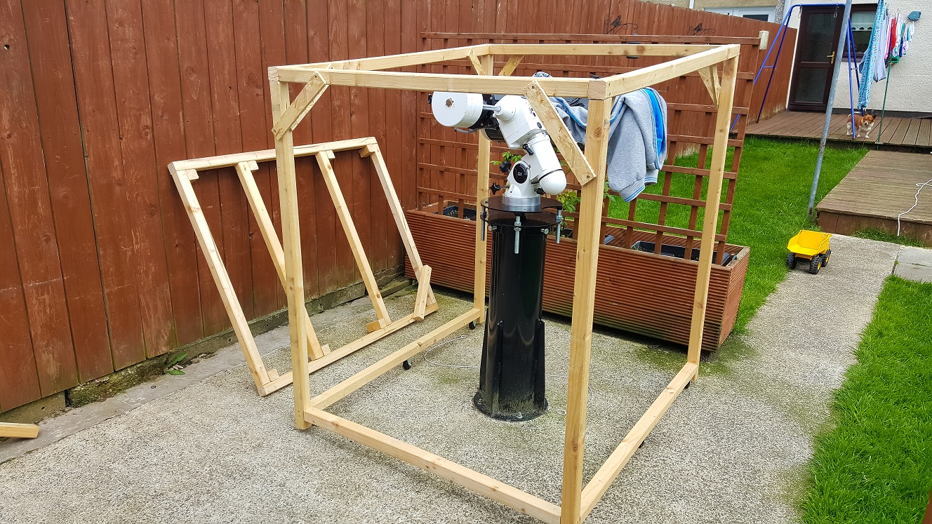
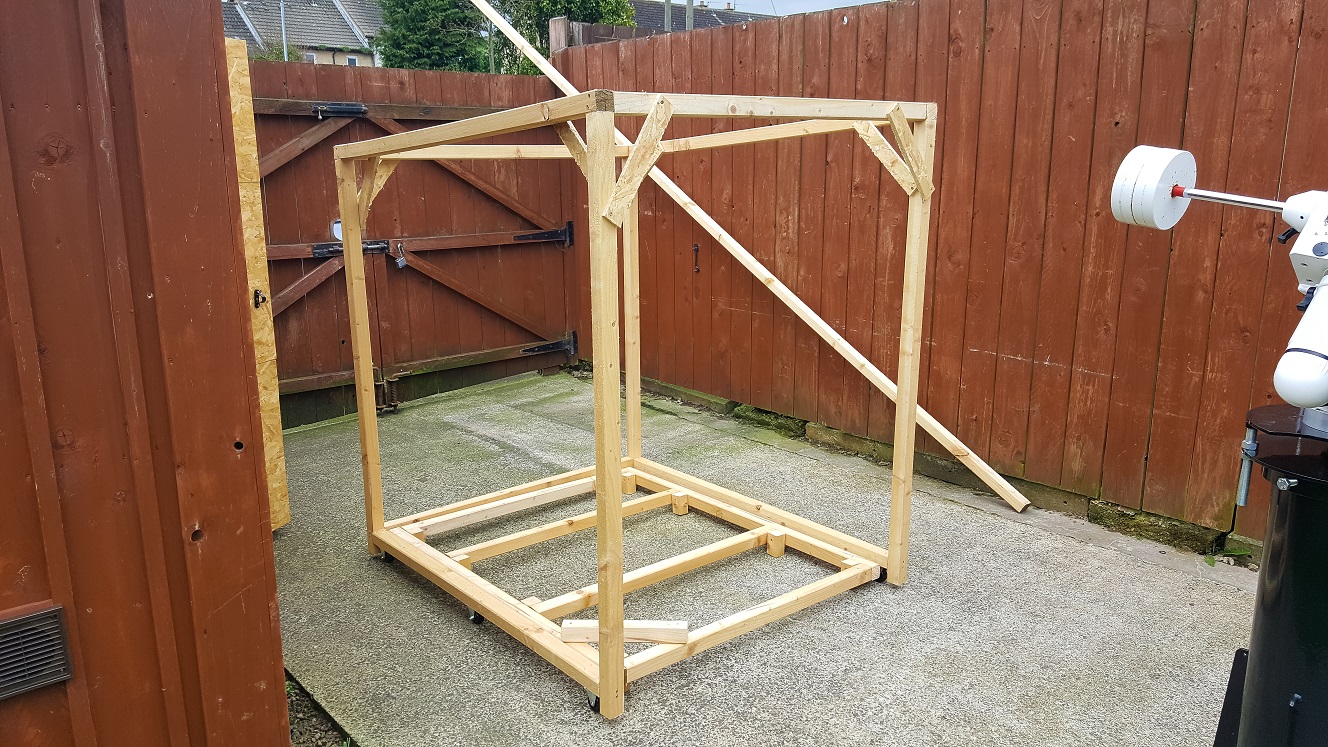
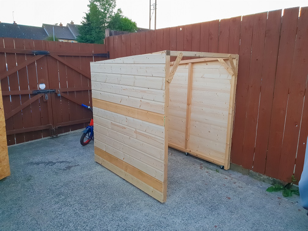
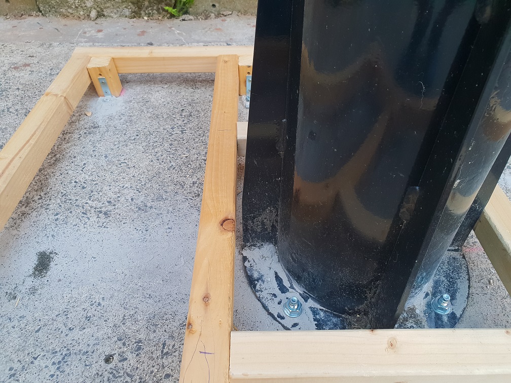
Once I had the base ready I quickly created the frame that would go around it. One of the challenges with a shed like this is that because it needs to roll-away, one of the sides must be completely open. This makes the entire shed a little more ‘wobbly’ than a normal shed would be.
Lesson learnt: If I was building this again I would create the shed with a brace at the bottom of the open side and simply remove this at the very end. This would allow everything to be built square and avoid lots of the braces I had to use.
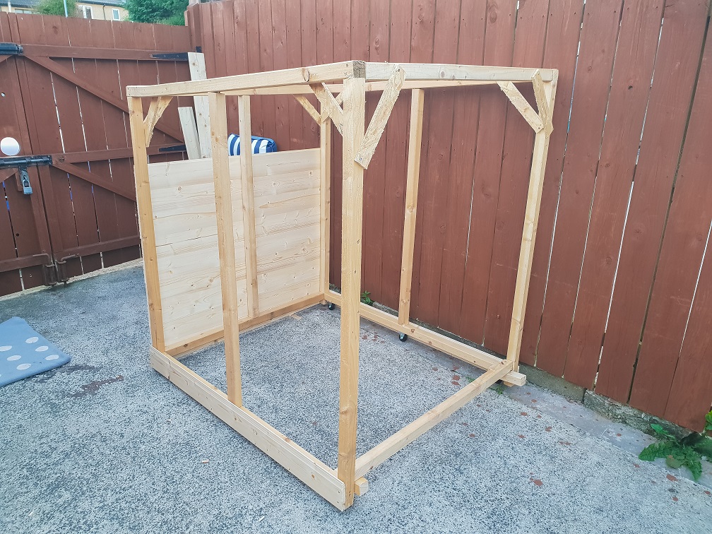
Once the frame was up I just needed to sheet it in using the weatherboard. A bit of a challenge here was to allow for the slope of the concrete, I spent around 45mins measuring and remeasuring to make sure I could maintain a nice consistent gap around the bottom of the removable shed without having a large gap. It was well worth the effort as it keeps the bottom looking nice and tidy.
The next step was to make the doors, the first stage of this is to make the frame that the weatherboard will be screwed to. I allowed 0.5” clearance at each side plus 1” in the centre and made the doors equal width. For this I made the door frame and screwed them to the shed frame with a 0.5” piece of board in between to keep the hinge gap consistent. I used a scrap piece of weatherboard as a brace to keep the door frames square.
Lesson Learnt: I should have added a second piece of 2x2” frame at the bottom to allow the hinge to be further up the door.
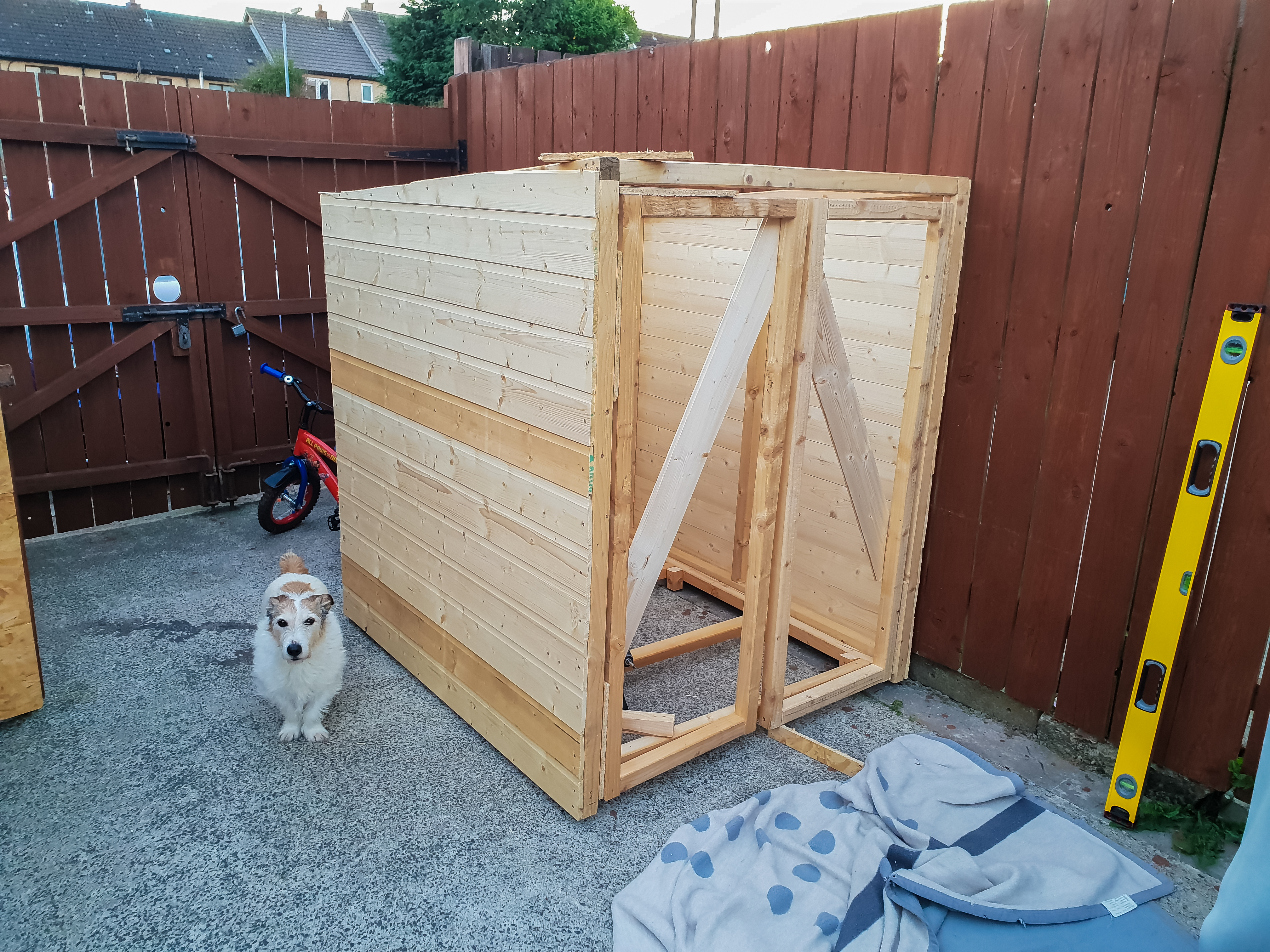
Once the door frames were solid and in place I measured and cut the weatherboard to suit. I used some thin 1” nails (tacks) to pin the weatherboard to the frame, my reasoning for this was that the door frames being secured to the main frame with only a couple of 3” screws would likely have fallen apart of lost shape if I had tried using the final 1.25” nails. Once all of the weatherboard, apart from the bottom piece, was tacked in place I fitted the hinges and measured up the slope I needed to allow for the concrete run-off. I then removed the doors so I could use the 1.5” nails to secure the tacked on weatherboard and the bottom piece. Then the doors were refitted.
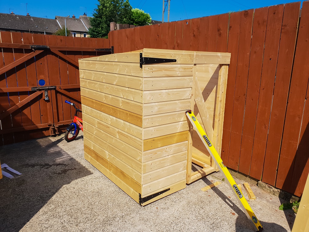
The next stage was to build the roof, again the first step of this was making a frame. I forgot to take a photo of my frame but it was basically a large square with 2 lengths inside in each direction. An important part of my roof design was to have a 1” gap all around the shed to allow any hot air inside the shed to flow out; meaning the shed would stay at the same temperature as outside, removing the need (hopefully) for me to cool down my scope before an imaging session.
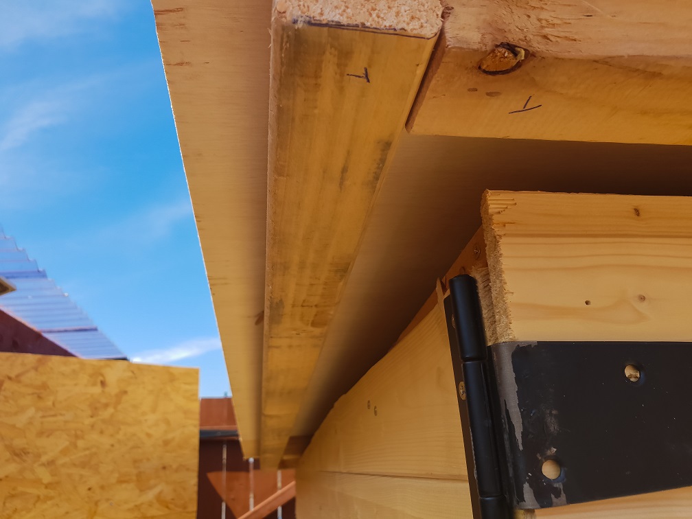
Next was to felt the roof, this was something I hadn’t done before. I was a little apprehensive about it but it was much easier than I expected. I chose to clamp the felt from underneath the roof using a lath. The rule for felting would be to start with the lower portion of the roof slope and work toward the top, laying the felt across the roof rather than up the slope, with at least a 4” overlap. Fortunately I only needed two pieces so just one overlap which was around 12”.
I laid the first piece of felt and clamped it at the lower end of the roof using the lath, this allowed me to slide the felt down off the roof, with the lath holding it in place, while I painted on the adhesive. Once the adhesive was on I rolled the hanging felt up and pushed it back over the roof. I followed the same process for the felt at the top of the roof.
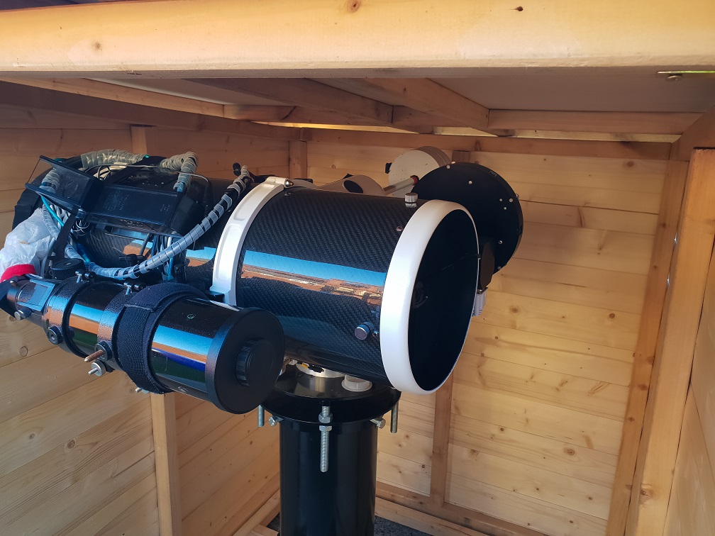
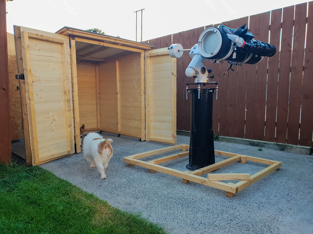
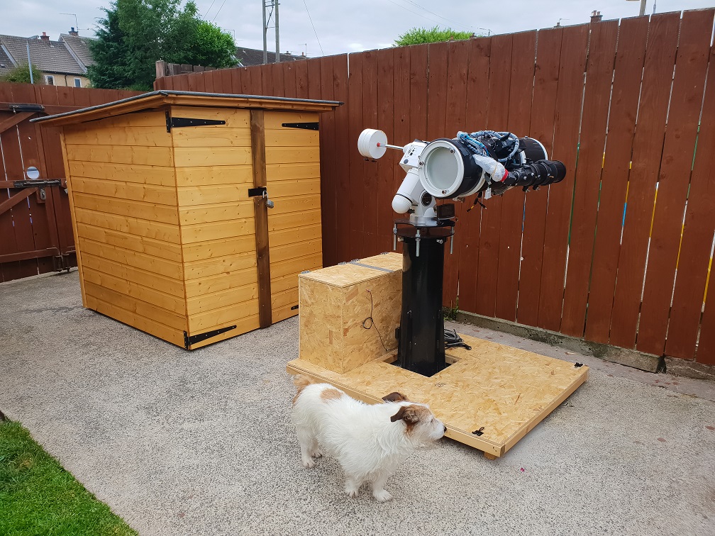
At this point I decided to do a test fit with the telescope fitted to the mount, fortunately it was a success!
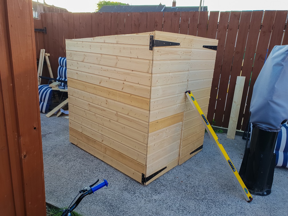
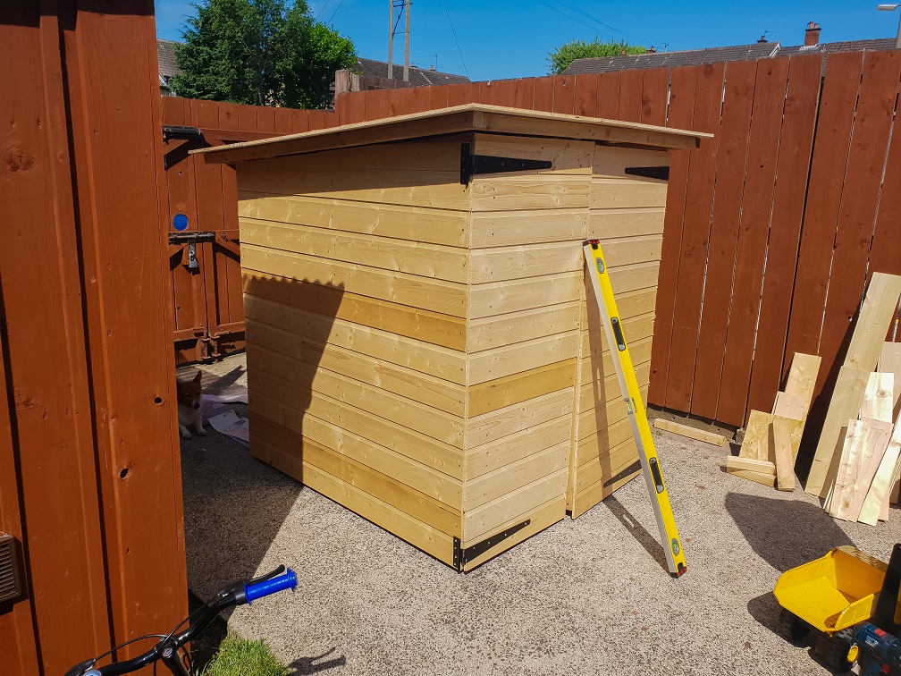
I left the adhesive to dry overnight and trimmed off the excess the next evening. I also fitted the 4” astragal to the main door along with the hasp and staple plus a drop bolt to top of the slave leaf.
Time for another test fit.
Now that the main body of the shed was finished I needed to measure how far I would have to move my pier so the shed would be close to my fence, again an attempt to not waste playing space for my kids. This was another task I dreaded, due to the weight of the pier, but much like felting the roof, it was not overly difficult or time consuming.
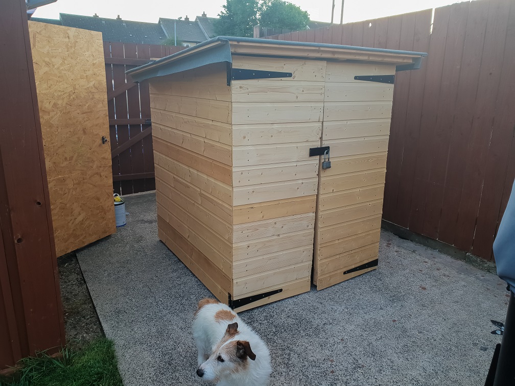
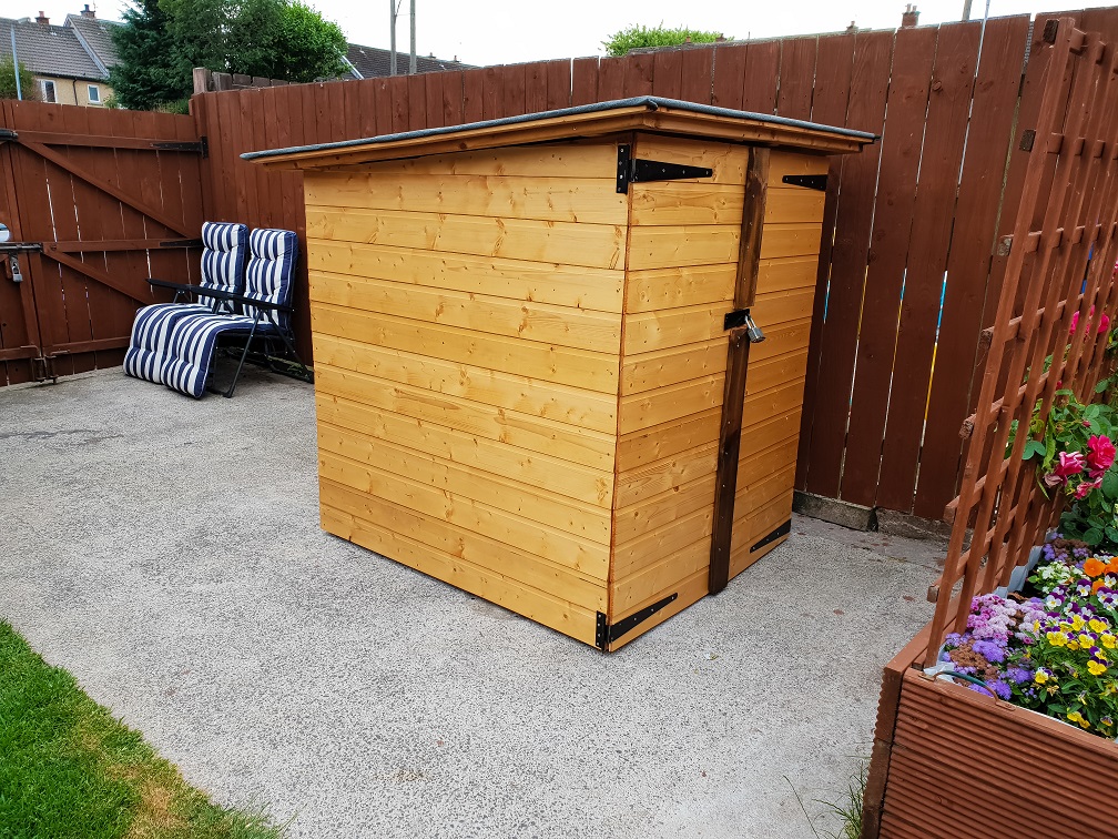
With the pier moved I put the shed in its final position and locked it up for the night.
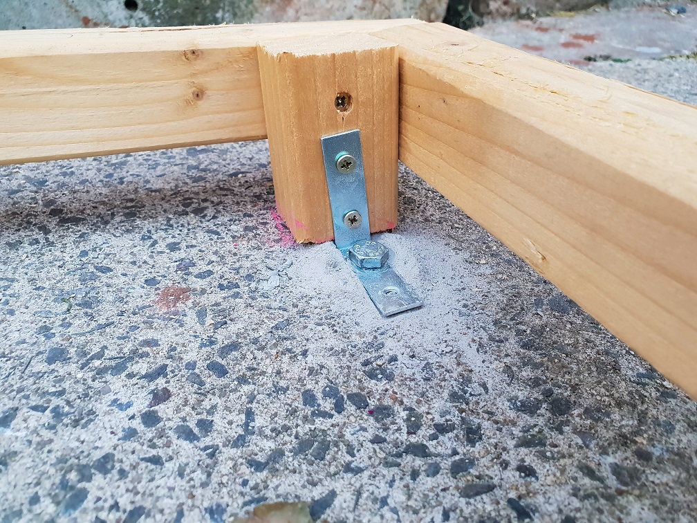
With the main shed body pretty much finished, aside from a few flashings and painting I turned my attention to securing the base to the concrete. For this I used some 4” concrete screws and some 50mm L-brackets out of my local Screwfix shop. They weren’t the easiest to fit but they will certainly hold the base in place. I fitted 8 bolts in total.
Once the base was secured I finished off the support for the flooring. An important detail here is to have the support close to but not touching the pier, this avoids any vibrations that might result in you walking on the base.
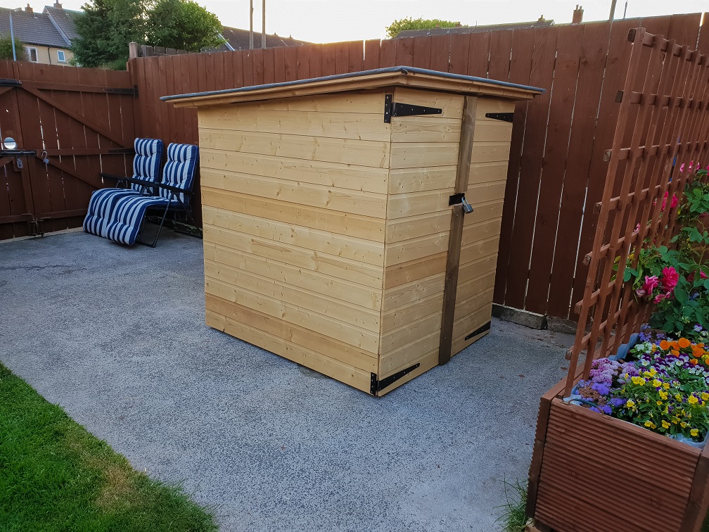
The next stage for me was to give the outside of the shed a couple of coats of solvent based wood stain. The solvent based stain is more expensive than the water based variety but I find it goes further and gives a better finish on good quality wood like weatherboard. I tend to use water based stain for rough wood like fences, etc.
Next up was to sheet the floor, after doing the roof with a handsaw I decided to borrow a friends rip-saw to make life easier... and MUCH faster. I added a few extra supports underneath since I was using 12mm sheet for the flooring. Normally I would have used 18mm sheet but I had lots of 12mm off-cuts from last years summer project so I wanted to make use of that. I kept the sheets 2-3mm back from the edge of the frame, my thinking was that it would be less likely take a bump and split.
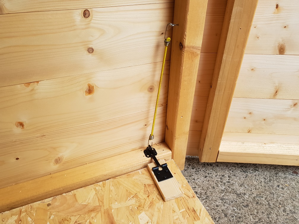
Then it was mostly finishing off by adding a bottom drop-bolt to the slave door and adding a hasp & staple to each side so that the main shed was secured to the floor.
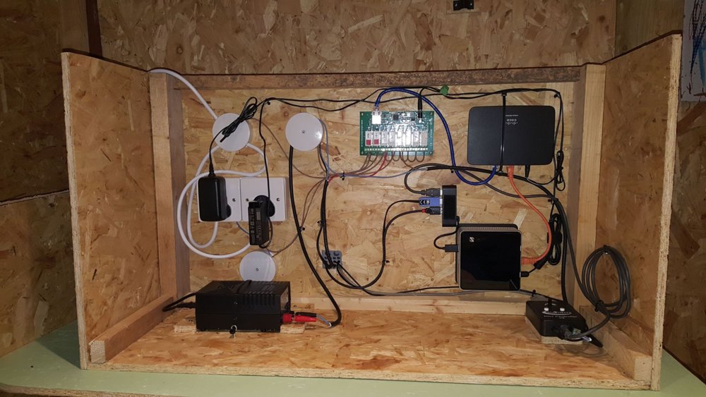
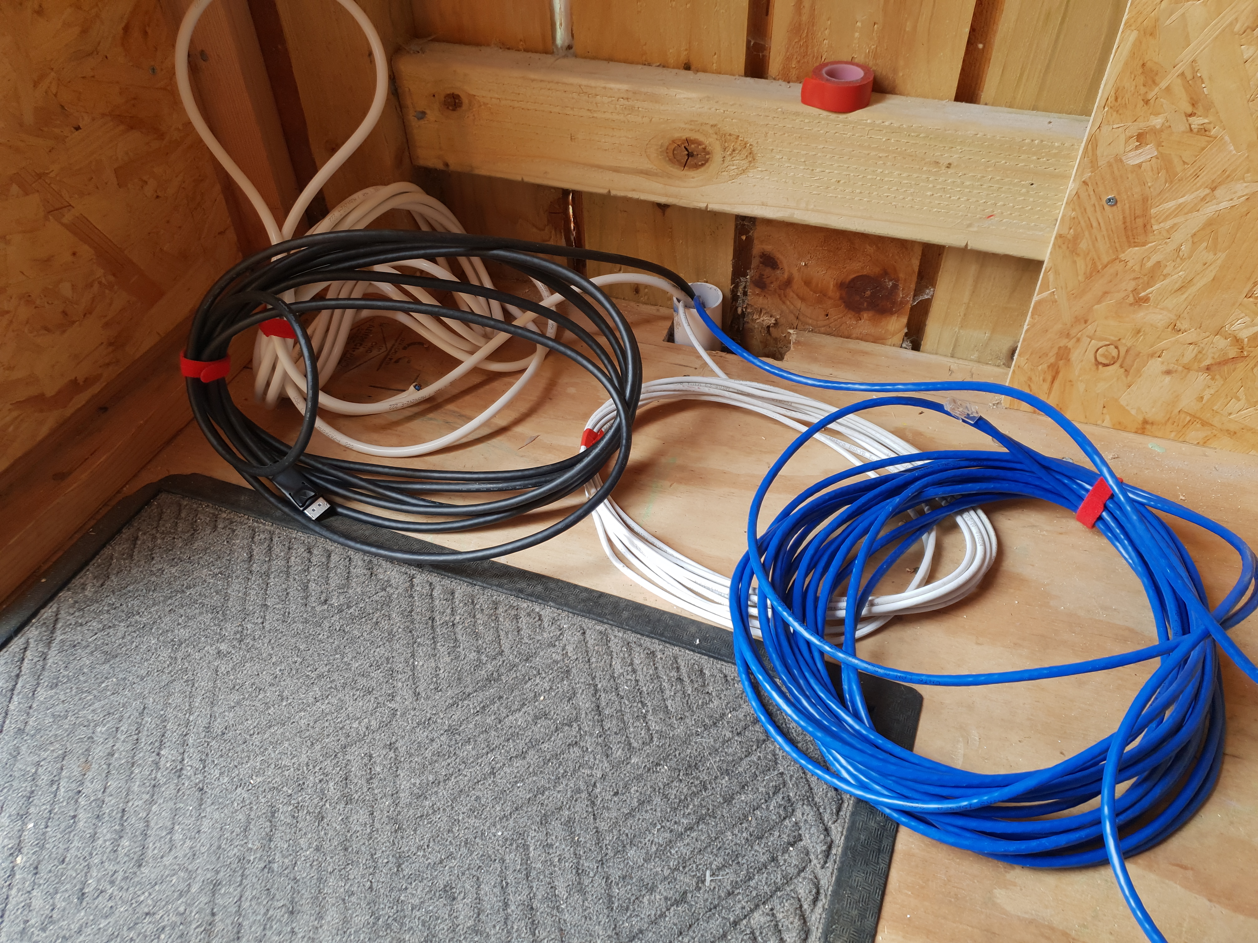
Once I had fitted the main control box that houses electronics that was basically the shed done.
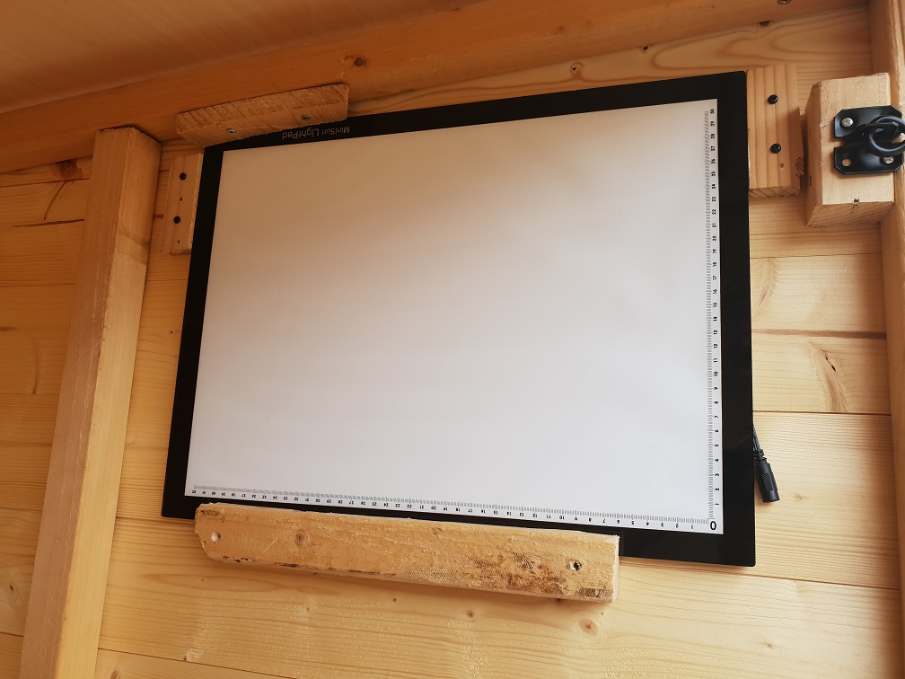
Next I added my LED tracing pad to the inside wall where the scope would be pointed when parked, I use this for taking flats at the end of an imaging session. It seems like a relatively inexpensive and consistent way to generate flats. Initially I found that the panel was too bright for my CCD so I used a cheap 'buck converter' to drop the input voltage down from 12v to 8.5v.
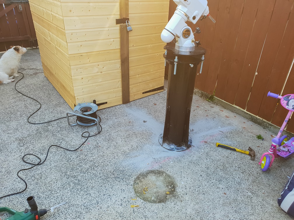
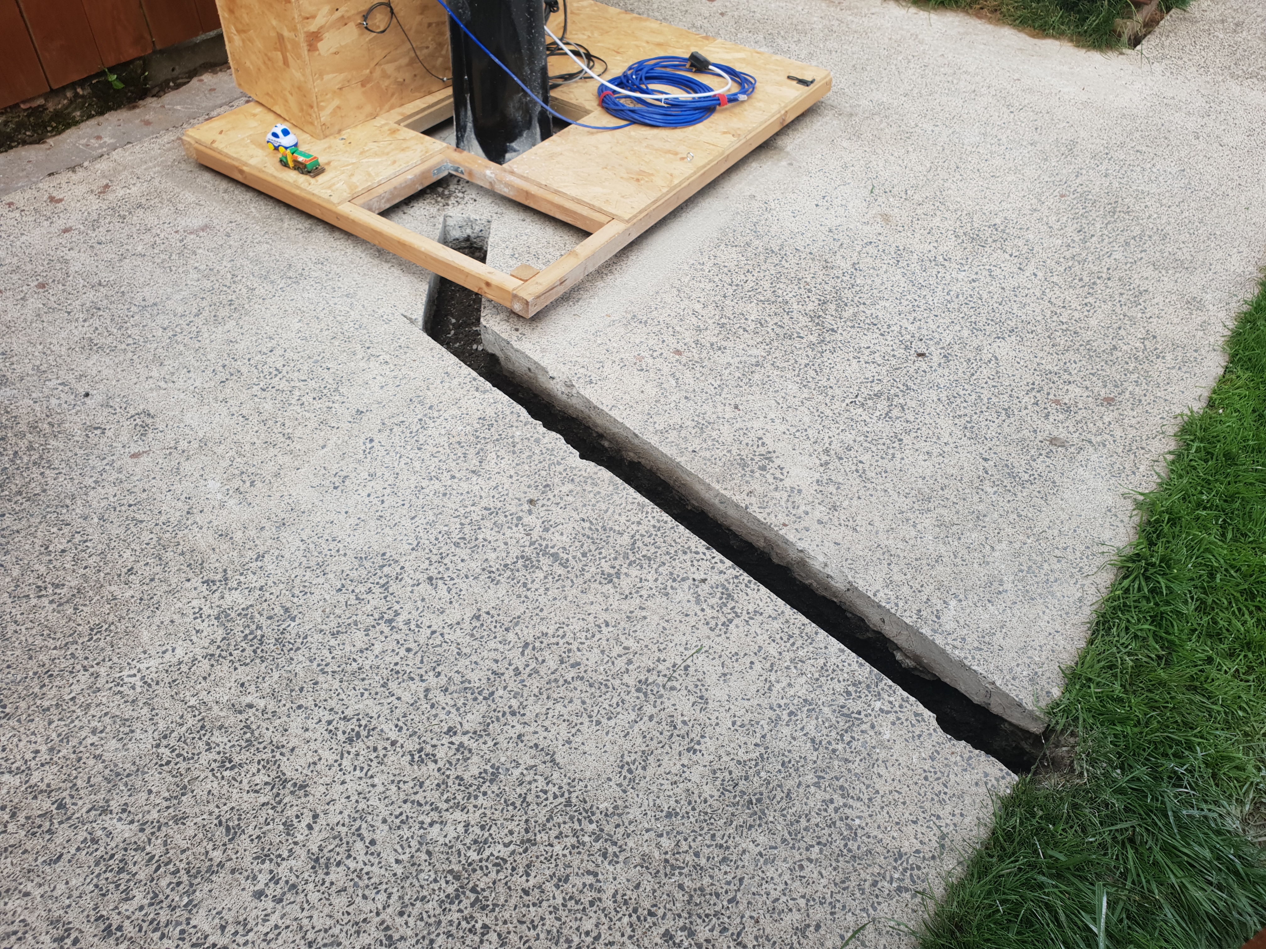
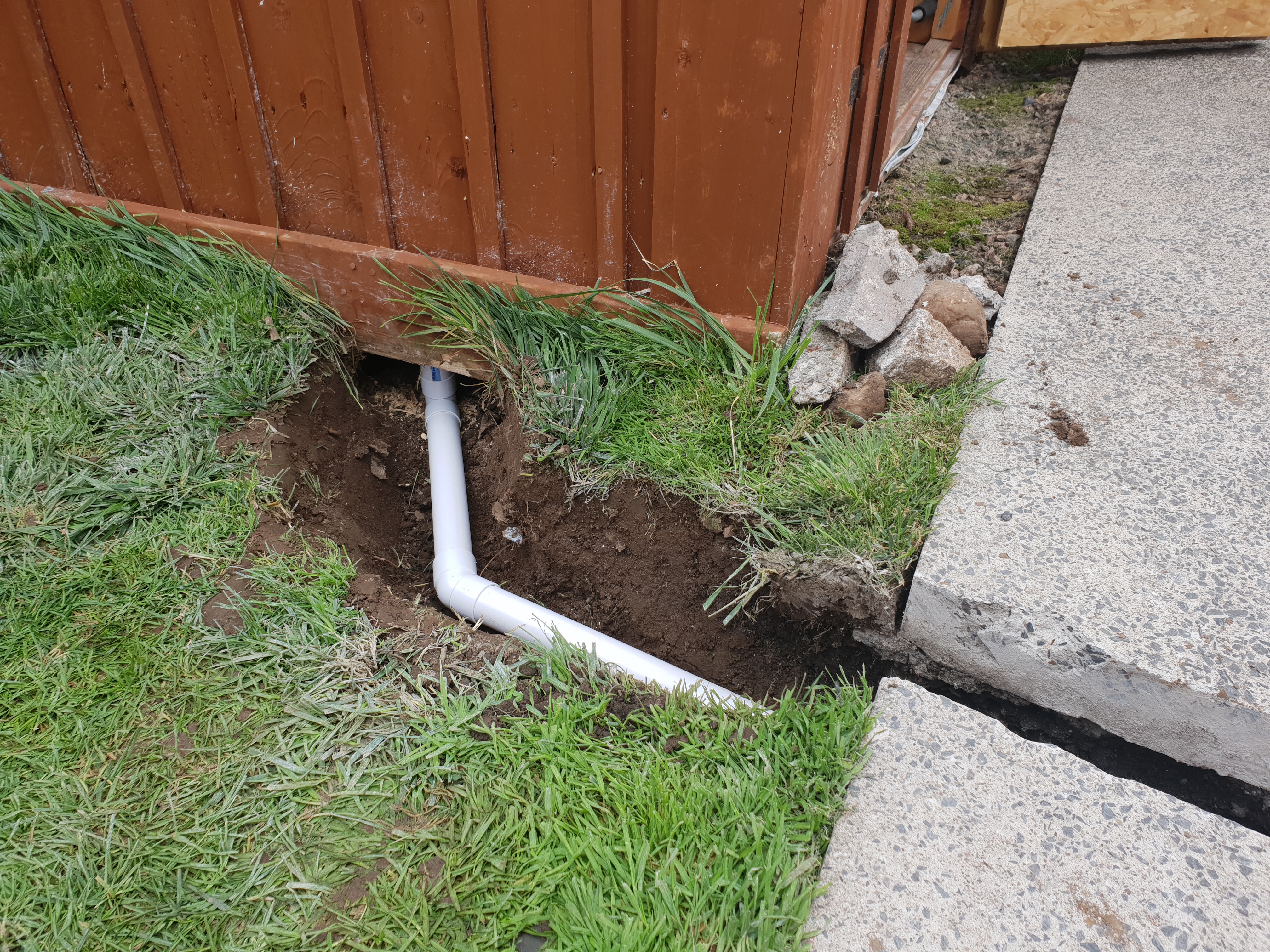
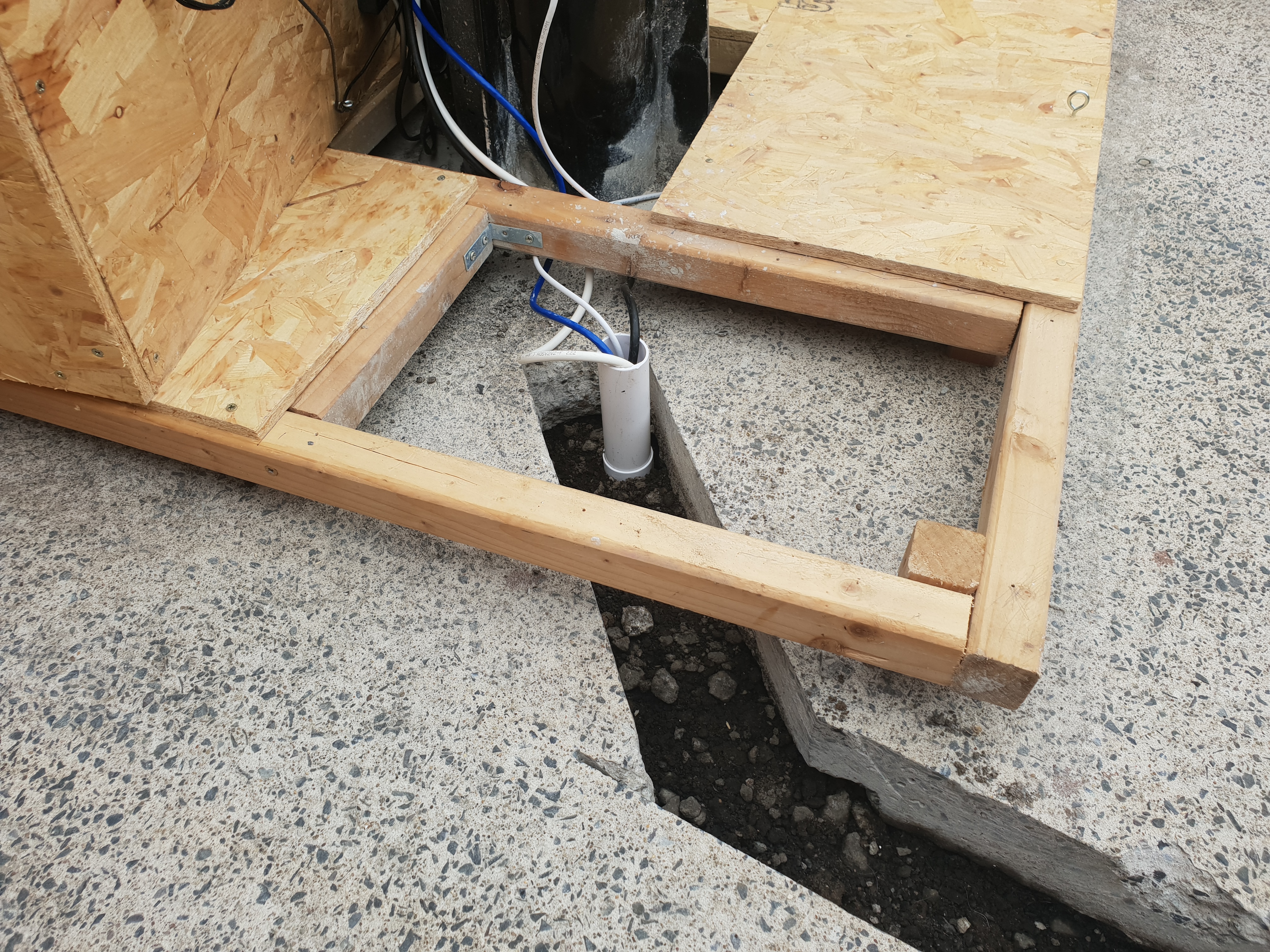
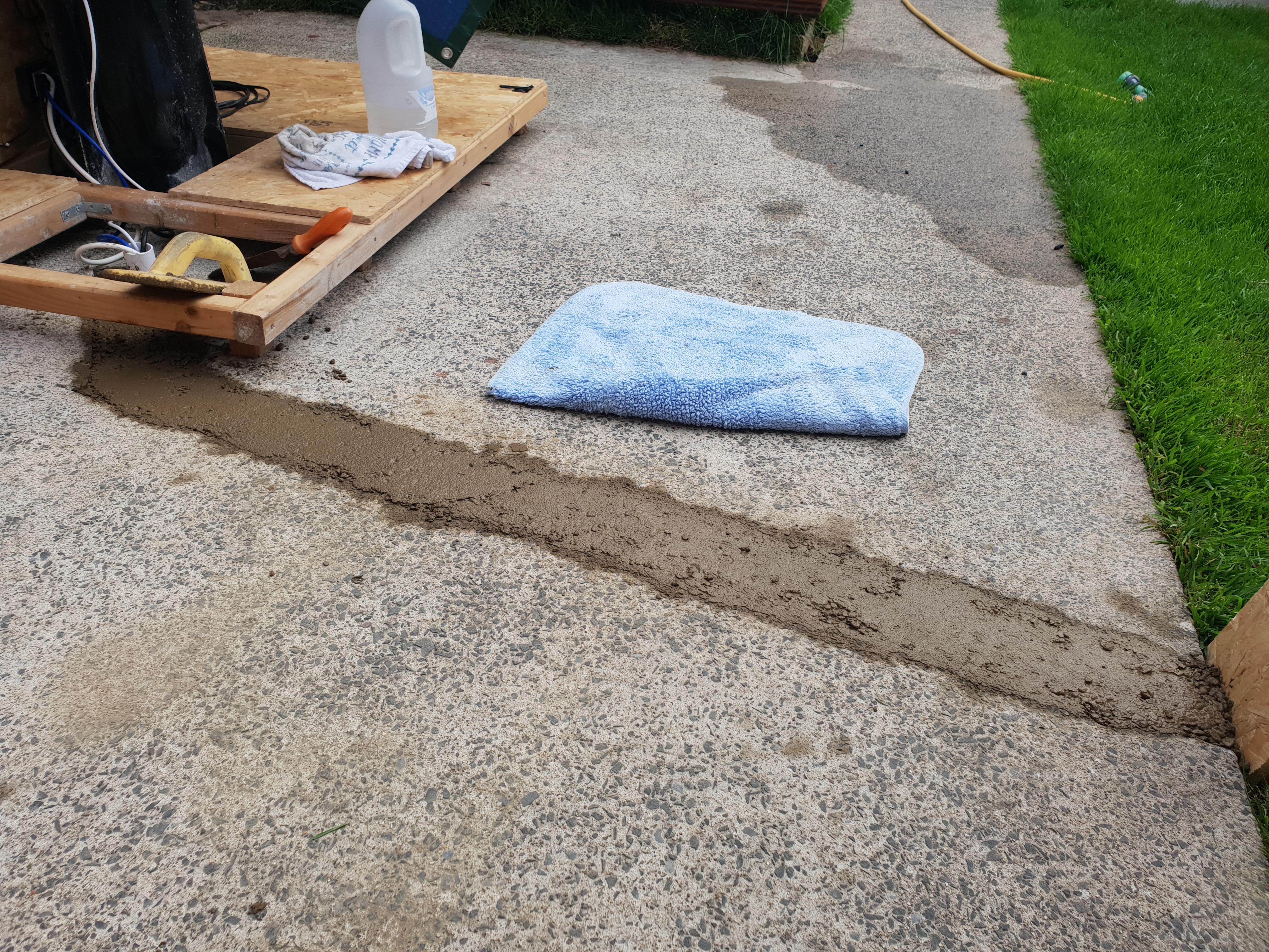
The next stage was to cut a track in the concrete and bury a 40mm pipe that I can use to run mains cable and network cable into the control box. To do this I needed to hire a Stihl concrete saw, cutting the concrete was extremely dusty but it did the job well.
Then I just had to fill in the track with some ready-mix concrete.
And that was it done, ready for some clear skies!
I hope you found this guide useful, if you have any questions please feel free to drop me an email.